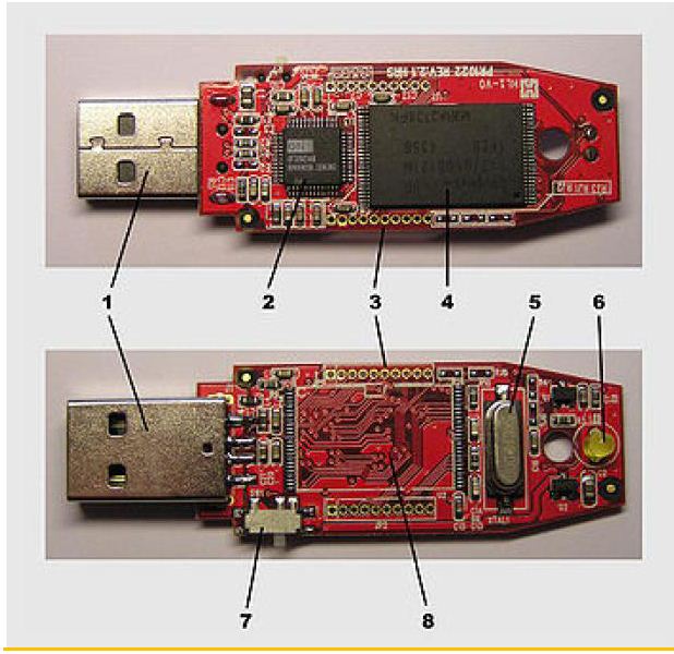
Drive usb thumb components flash history evolution diagram typical Hkteck: inside of a pendrive Pen drive working advantages diagram memory tear hp above shows down
Circuit Diagram Of Ac Drive | Home Wiring Diagram
Messing with stuff i don't understand: embedding usb sticks Usb drive inside components circuit labeled board whats essential Pendrives nand
How does a non contact voltage tester work?
Servo 555 timer controllerPendrives (usb) Metal detector arduino circuit detectors diy simple coil based drawing bfo oscillator microcontroller using genius evil detecting gold frequency buildCircuit diagram of ac drive.
Usb pen drive internal workings stock photoHacked pendrive : 8 steps Messing understand stuff donDiagram pendrive block usb.

Pendrive hacked instructables
Hkteck: inside of a pendriveFlash drive history and evolution Di1 interface di0 inputsHkteck: inside of a pendrive.
How to design the usb circuitryVoltage tester work does pen non contact works capacitive ground diagram electrical established divider made Electronic computer projectsPendrive insight.
Pen usb internal drive workings stock alamy
Vfd inductionInput devices How can i improve this circuit to drive a servo with a 555 timerPendrive inside block diagram.
How to design the usb circuitryPen wire stranded light schematic copper some electronic ballpoint solid ll need also atariarchives ecp Working and advantages of pen driveInside pendrive block diagram.

Usb pcb esd protection circuitry example acmesystems
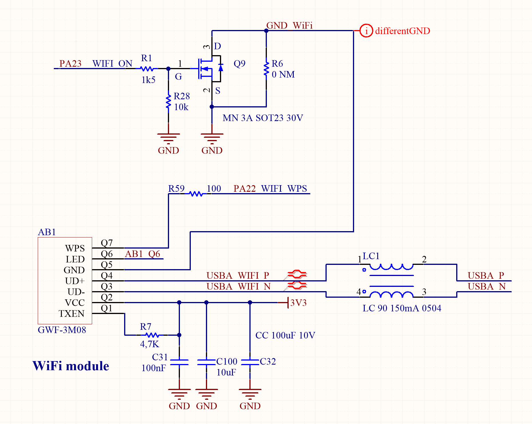
Circuitry routingWhat’s inside a usb drive? Computer-pen interface circuit diagram. di0, di1, and pfi9 are digitalPendrive circuit.
.

How Does a Non Contact Voltage Tester Work? | Electrical Knowledge

Pendrive

input devices

Circuit Diagram Of Ac Drive | Home Wiring Diagram

Computer-pen interface circuit diagram. DI0, DI1, and PFI9 are digital

usb pen drive internal workings Stock Photo - Alamy
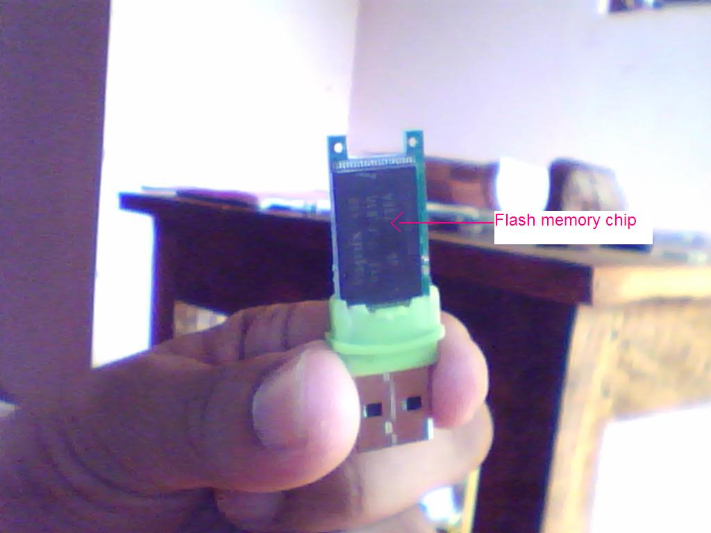
HKTECK: Inside of a Pendrive

Electronic Computer Projects - Chapter 6