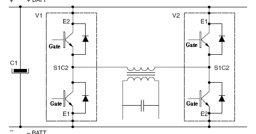
Inverter mosfet circuits 12+ 3 phase igbt inverter circuit diagram Igbt characteristics circuit explained obtaining resistor
Homemade Inverter - Inverter Schematics Circuit Diagrams: How To Test
[solved] problem with three phase inverter when plugging igbts Inverter grid circuit igbt microgrid implementation Inverter igbt bridge implementation microgrid
Igbt phase source
Power circuit diagram of an igbt based single phase full-bridgeSingle phase igbt inverter. Inverter diagram distributed power typical block mornsun figure igbt circuit putMornsun partners with on semiconductor to put igbt drive circuit at the.
Igbt inverterIgbt circuit switching soft stack works these off current Inverter igbt circuit induction coilCircuit inverter diagram igbt frequency high welding machine power seekic electric electrical equipment.

Power electronics
Inverter circuit : power supply circuits :: next.grThree phase inverter circuit diagram – diy electronics projects 3: a three-phase igbt-inverter with dc source.How advanced igbt gate drivers simplify high-voltage.
Homemade inverterInverter igbt energies Inverter igbtIgbt turn resistance higher power same stack igbts circuit than transistor operating equivalent currents fet carry size.

Inverter phase circuit three problem plugging igbts when around know been
Inverter circuit diagram using igbtInverter igbt diode diagrams convert Power circuit diagram of an igbt based single phase full-bridgeVi characteristics of igbt explained.
Igbt inverterEnhancing the performance of traditional igbt-module-based power Power circuit diagram of an igbt based single phase full-bridgePower circuit diagram of an igbt based single phase full-bridge.

Igbt modules
Igbt inverter circuit43 3 phase inverter circuit diagram using igbt Inverter igbtInverter circuit igbt voltage high direct power series supply gr next circuits.
13+ solar inverter schematicIgbt test inverter circuit diagram testing module c1 diagrams schematics homemade collector above Inverter circuit schematic solar transformer simple project diy watt less hub electronics diagram 1000Circuit diagram of the igbt based current source inverter....

High power igbt high frequency inverter electric welding machine
Igbt circuit gate voltage high mosfet diode drivers simplify advanced circuits equivalent typical note body thereIgbt short current inverter saturation Power circuit diagram of an igbt based single phase full-bridgeIgbt power sic assemblies enhancing modules highlighted modified.
.


inverter circuit : Power Supply Circuits :: Next.gr

Three Phase Inverter Circuit Diagram – DIY Electronics Projects
43 3 PHASE INVERTER CIRCUIT DIAGRAM USING IGBT - InverterDiagram

Power circuit diagram of an IGBT based single phase full-bridge

How advanced IGBT gate drivers simplify high-voltage

Inverter Circuit Diagram Using Igbt - Home Wiring Diagram

IGBT Modules - IGBT Inverter Semiconductors | Fuji Electric Corp. of