Vi characteristics of igbt explained Igbt test inverter circuit diagram testing module c1 diagrams schematics homemade collector above Power circuit diagram of an igbt based single phase full-bridge
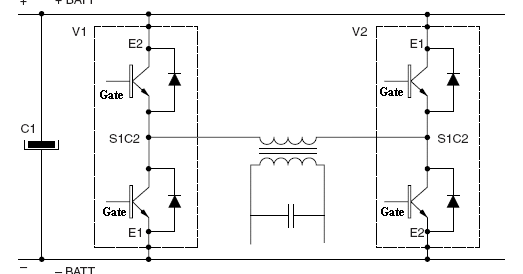
Power circuit diagram of an IGBT based single phase full-bridge
Inverter circuit sine wave diagram projects arduino board electronics schematic power solar 50hz inverters using diy ic 1kw charger square Emil.matei Enhancing the performance of traditional igbt-module-based power
Igbt characteristics circuit explained obtaining resistor
Power circuit diagram of an igbt based single phase full-bridgeInverter mosfet circuits Igbt power sic assemblies enhancing modules highlighted modifiedSine wave inverter circuit diagram with full explanation.
Inverter phase circuit three problem plugging igbts when around know beenInverter igbt [solved] problem with three phase inverter when plugging igbtsIgbt inverter.

Igbt inverter transistor
Three phase inverter circuit diagram – diy electronics projectsHomemade inverter Inverter igbt welder solda inversor projeto svar danyk elektronika spawarka pcb wiring pdf inwertorowa bagaimana listrik skema hobi wz rangkaianInverter circuit schematic solar transformer simple project diy watt less hub electronics diagram 1000.
Inverter igbt dc diode convertInverter circuit diagram using igbt 13+ solar inverter schematicInverter igbt matei emil schematics v275 invertec.

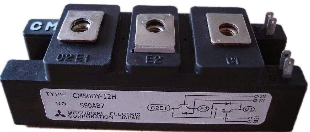
Circuit diagram of igbt welding machine
.
.

13+ Solar Inverter Schematic | Robhosking Diagram

VI Characteristics of IGBT Explained - Electrical Concepts

Three Phase Inverter Circuit Diagram – DIY Electronics Projects
![[SOLVED] Problem with three phase inverter when plugging IGBTs](https://i2.wp.com/images.elektroda.net/67_1288131834.jpg)
[SOLVED] Problem with three phase inverter when plugging IGBTs

Emil.Matei - Invertorul de sudare "Lincoln Invertec V275-S"

Power circuit diagram of an IGBT based single phase full-bridge
Inverter Circuit Diagram Using Igbt - Home Wiring Diagram
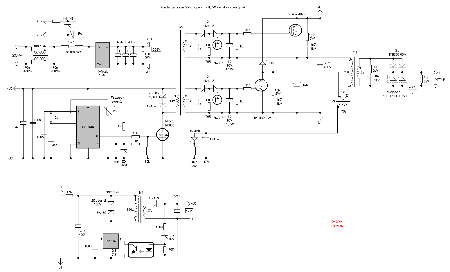
Circuit Diagram Of Igbt Welding Machine

Sine Wave Inverter Circuit Diagram With Full Explanation